Guest access – Cisco Wireless Controller
In this topic, you will learn how to configure a Cisco Wireless Controller to work together with the Portnox™ Cloud captive portal for guest user authentication.
Cisco Catalyst 9800 Wireless LAN Controller (IOS-XE)
Before you begin configuring your wireless controller, you must:
-
Create Cloud RADIUS servers and note down the following values: Cloud RADIUS IP, Authentication port, Accounting port, and Shared Secret.
-
Configure the guest network in Portnox Cloud and note down the values of the fields: IP (for walled garden) and Captive Portal URL.
-
In the Create AAA Radius Server window, enter the RADIUS server details:
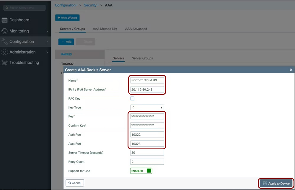
- In the Name field, enter the name of this server, for example, Portnox Cloud US.
- In the IPv4 / IPv6 Server Address field, enter the Cloud RADIUS IP value copied from the Cloud RADIUS server configuration.
- In the Key and Confirm Key fields, enter the Shared Secret value copied from the Cloud RADIUS server configuration.
- In the Auth Port field, enter the Authentication port value copied from the Cloud RADIUS server configuration.
- In the Acct Port field, enter the Accounting port value copied from the Cloud RADIUS server configuration.
- Click on the Apply to Device button.
Note:If you want to use more than one Cloud RADIUS server, repeat the steps above for the second server. -
In the Create AAA Radius Server Group window, configure the RADIUS server group details:
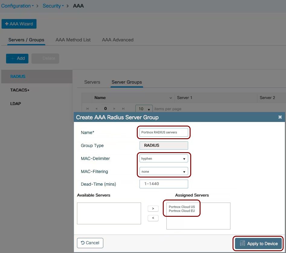
- In the Name field, enter a name for this group.
- In the MAC-Delimiter field, select the hyphen option.
- In the MAC-Filtering field, select the none option.
- Use the > button to move all Portnox Cloud servers from the Available Servers list to the Assigned Servers list.
- Click on the Apply to Device button.
-
In the Quick Setup: AAA Authentication window, configure the AAA authentication list
details:
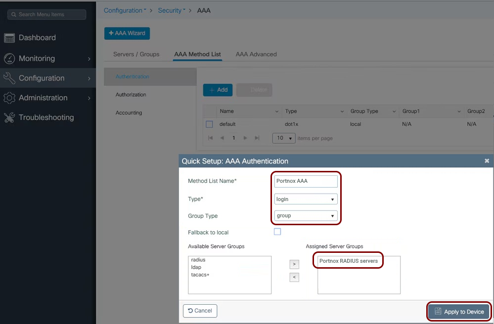
- In the Method List Name field, enter a name for this method list.
- In the Type field, select the login option.
- In the Group Type field, select the group option.
- Use the > button to move the Portnox Cloud RADIUS server group from the Available Server Groups list to the Assigned Server Groups list.
- Click on the Apply to Device button.
-
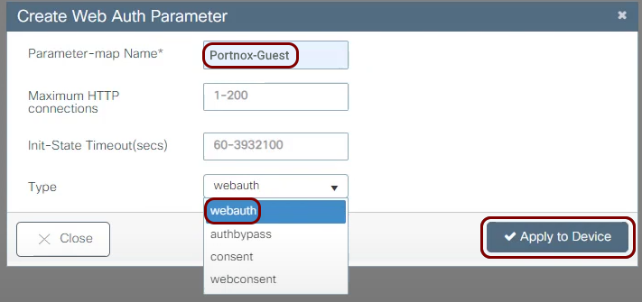
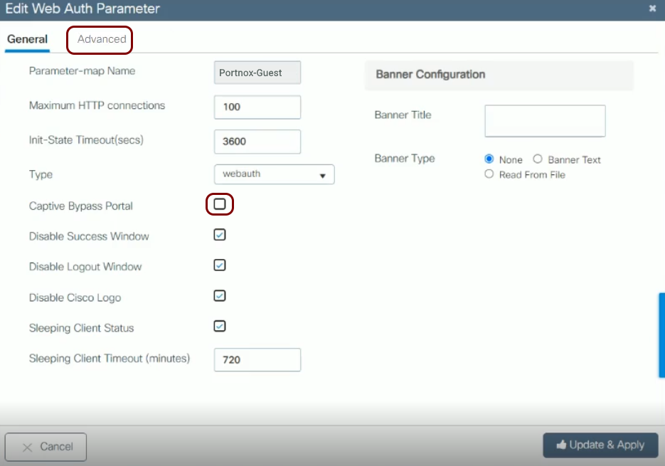
In the Create Web Auth Parameter window, enter a Parameter-map Name,
and in the Type field, select the webauth option. Then, click on the
Apply to Device button.
-
Select and open the newly created parameter map to edit it, and make sure that the Captive Bypass
Portal checkbox is not active. Then, click on the Advanced tab.
You can also optionally set the Banner Title.
-
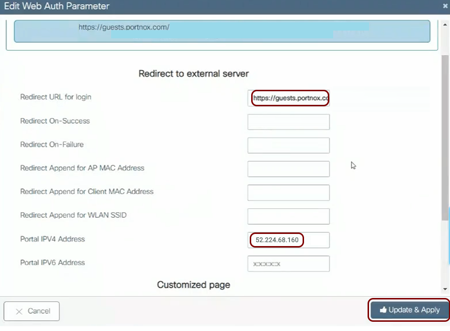
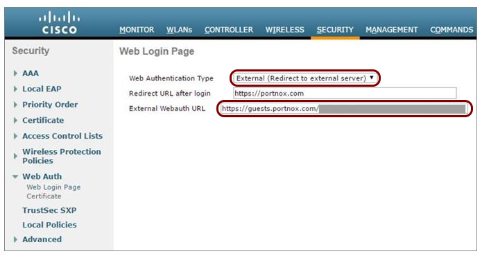
In the Redirect to external server section:
-
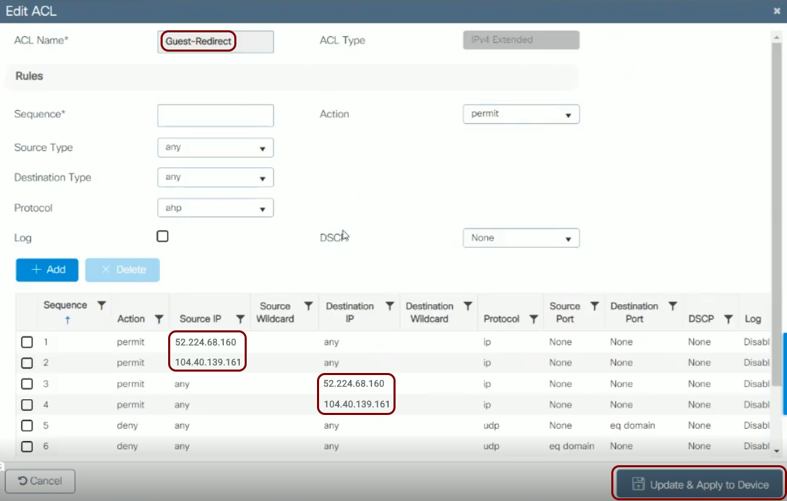
Navigate to and add or edit an ACL (access control list) that you will use as a pre-authentication ACL for the
captive portal.
 Warning:The NAS device must be able to communicate with the walled garden IP addresses at all times. If this communication is blocked in any way, the captive portal will not work, and guest devices will be unable to connect to the network. Before you proceed, verify that all firewalls, ACLs, and any other security measures that could interfere with this communication are configured to explicitly allow the walled garden IP addresses.
 -
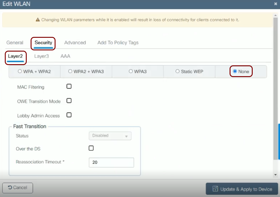
In the Add WLAN or Edit WLAN window, in the tab, choose the None option and leave the default values for other
settings.
-
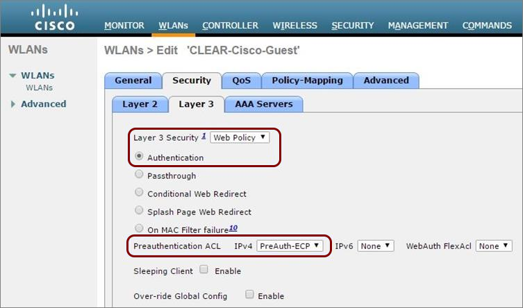
In the Layer 3 tab:
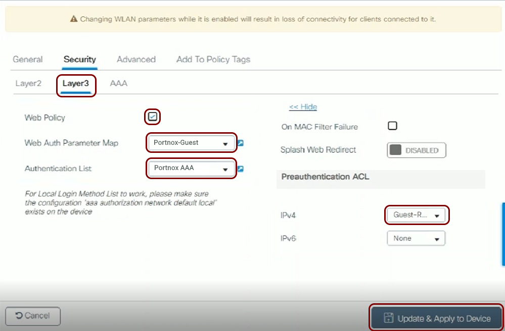
- Activate the Web Policy checkbox.
- In the Web Auth Parameter Map field, select the parameter map that you created earlier.
- In the Authentication List field, select the AAA authentication list that you created earlier.
- In the Preauthentication ACL section, in the IPv4 field, select the preauthentication ACL that you created earlier.
- Click on the Update & Apply to Device button.
Cisco AireOS Wireless LAN Controllers
Before you begin configuring your access point, you must configure the guest network in Portnox Cloud and note down the values of the fields: IP (for walled garden) and Captive Portal URL.
-
In the RADIUS Authentication Servers > Edit window that appears:
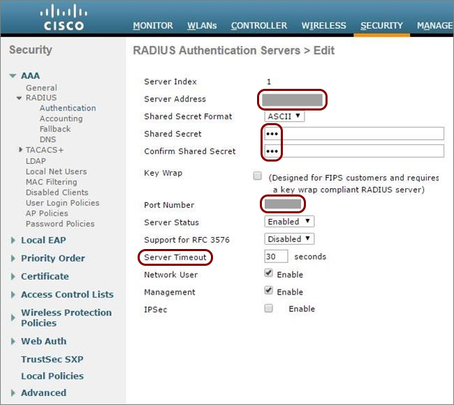
- Enter your Portnox Cloud RADIUS details that you noted down when creating your RADIUS server.
- Set the Server Timeout to 30 seconds.
- Optional: Repeat this for the second RADIUS server, if needed.
-
In the RADIUS Accounting Servers > Edit window that appears:
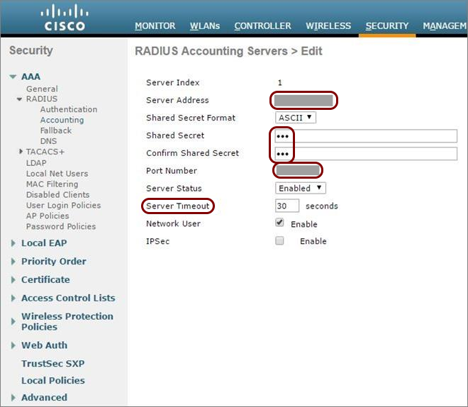
- Enter your Portnox Cloud RADIUS details that you noted down when creating your RADIUS server.
- Set the Server Timeout to 30 seconds.
- Optional: Repeat this for the second RADIUS server, if needed.
-
In the Access Control List > Rules window, click on Add New Rule to add
each of the following two rules:
-
For the first rule:
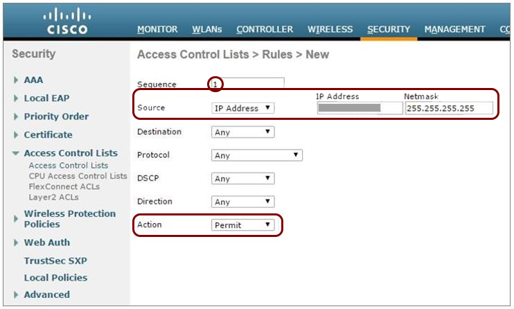
In Sequence, enter 1.
-
In Source, enter the first IP address for walled garden that you obtained when you configured the guest network in Portnox Cloud.
-
In Action, select Permit.
-
For the second rule:
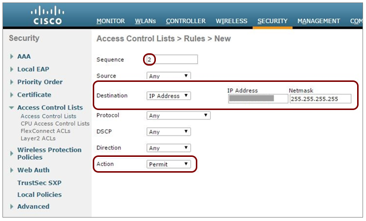
In Sequence, enter 2.
-
In Destination, enter the same first IP address for walled garden.
-
In Action, select Permit.
-
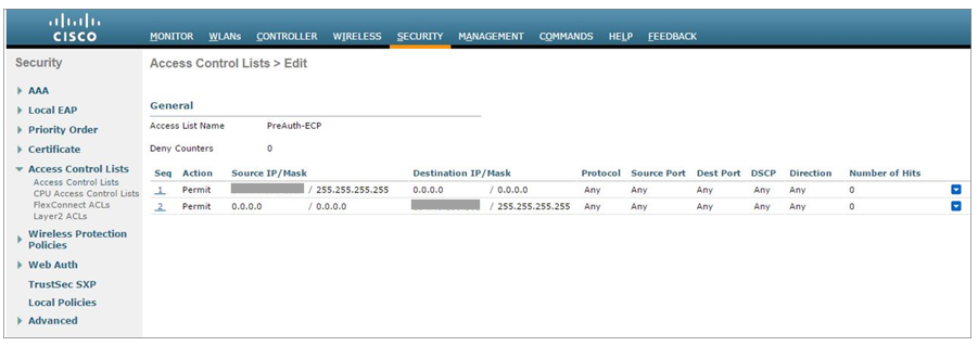
Click on Apply. Verify that the two rules are listed similarly to the rules shown
below.
-
For the first rule:
-
Navigate to and then:
-
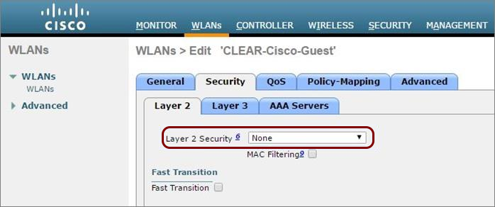
Navigate to WLANs and select the WLAN to be secured or create a new WLAN.
-
In Layer 2 Security, select None.
-
In Preauthentication ACL, select the access control list you created earlier.
-
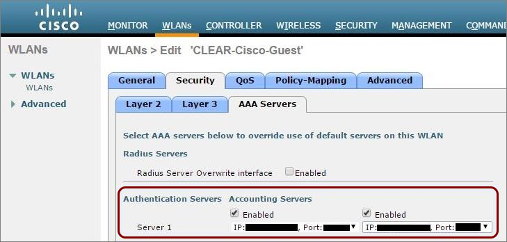
Select the RADIUS authentication server and the RADIUS accounting server that you added earlier.
-
Navigate to and select the virtual interface.
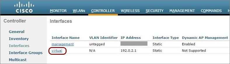
-
Check the value in the virtual interface’s DNS Host Name
field:
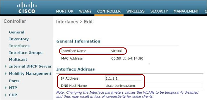
-
If a DNS Host Name is listed, make sure there is a DNS record for the listed host name on your local DNS server (this is a Cisco requirement).
-
If the DNS Host Name field is empty, continue to the next step.
Note:The IP address of the virtual interface must be an address from one of the private IP ranges. We recommend that you use an IP address from a range that is not used in your internal network infrastructure, or make sure that this IP address is not used by any other interface in your network. -
-
In Layer 2 Security, select None.
- Optional:
Configure the re-authentication timeout for the guest WLAN (the maximum time the device session remains active
before requiring re-authentication):
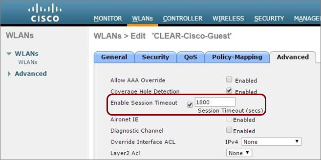
- Navigate to WLANs, select the relevant WLAN, and select the Advanced tab.
- In the Advanced tab, select the Enable Session Timeout checkbox and set the Session Timeout value.