Guest access – Fortinet
In this topic, you will learn how to configure Fortinet controllers to work together with the Portnox™ Cloud captive portal for guest user authentication.
Before you begin configuring your controller, you must do the following in Portnox Cloud:
-
Open the Cloud RADIUS configuration, select your primary RADIUS instance, and copy the following values: Cloud RADIUS IP, Authentication port, and Shared Secret.
-
Configure the guest network in Portnox Cloud and note down the values of the fields: Captive Portal URL and IP (for walled garden).
Save these values in a temporary text file or keep your Portnox Cloud configuration open in another browser tab for easy copying and pasting.
Also, in the Fortinet web interface, make sure that your access points are authorized ().
You can create a captive portal configuration on Fortinet controllers in one of two modes: the local bridge mode or the tunnel mode. To create a captive portal configuration:
- First, follow the steps to create the RADIUS server (common for both modes)
- Then, optionally configure the TLS certificate (also common for both modes)
- Finally, select the mode that fits your network configuration.
In the local bridge mode, the controller is only responsible for configuration management. This mode is often used in teleworking, for example, if an employee uses a company access point at home. In the tunnel mode, all the traffic from the access point is tunnelled back to the controller.
Create the RADIUS server configuration
In this section, you will enter Portnox Cloud RADIUS server information in the Fortinet web interface and CLI.
-
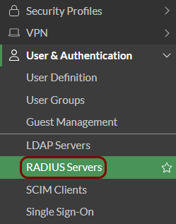
In the Fortinet web interface, in the left-hand side menu, click on the option to open the list of RADIUS servers.
-
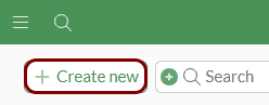
Above the SSID list, click on the Create New button.
-
In the New RADIUS Server pane, enter a Name for the RADIUS server. In
the Authentication method field, select the Specify option, and then
select the PAP option.

-
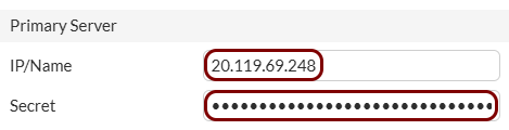
In the Primary Server section, paste the Cloud RADIUS IP value copied
from Portnox Cloud into the IP/Name field, and paste the Shared Secret
value copied from Portnox Cloud into the Secret field. Then, click on the
OK button to save the configuration.
- Optional:
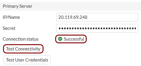
To test if your configuration change was successful, you can click on the RADIUS server name and then click on the
Edit button to edit it, and then click on the Test Connectivity
button in the Edit RADIUS Server pane.
Configure the TLS certificate
Optional: In this section, you will upload and configure your own TLS certificate so you can use the captive portal in HTTPS mode.
If you do not complete these steps, most devices will display a warning that the captive portal is not working in a secure mode. If you want to avoid such warnings, and run the captive portal in secure mode (HTTPS):
- Obtain a domain or subdomain for your captive portal
- Configure that domain or subdomain in your DNS server
- Obtain a TLS certificate for that domain or subdomain.
To follow the steps below, you will need:
- The domain or subdomain name
- The TLS certificate file for your domain or subdomain name together with the private key file (as a single PKCS#12 file or as two Base-64 encoded X.509 files)
- The CA certificate file for the issuer of your TLS certificate in the Base-64 encoded X.509 format.
-
Import the certificates:
-
In the left-hand side menu, click on the option to open the list of certificates.
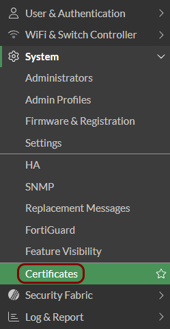 Note:If the option Certificates is not visible, go to Feature Visibility and activate .
 -
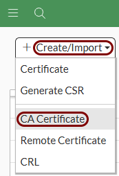
Above the certificate list, click on the Create/Import button, and then select the
CA Certificate option.
-
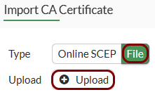
In the Import CA Certificate pane, in the Type field, click on
the File option, and then click on the Upload button. Then,
select the CA certificate file for the issuer of your TLS certificate and click on the
OK button.
Result: Your issuer’s certificate will be listed in the Remote CA Certificate section as CA_Cert_1 or higher number if you already have custom CA certificates imported.

-
Above the certificate list, click on the Create/Import button, and then select the
Certificate option.

-
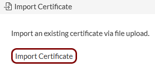
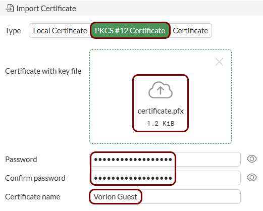
In the Create Certificate pane, click on the Import Certificate
button.
-
In the Import Certificate section, in the Type field, select
either the PKCS#12 option (if your certificate and private key are in a single file)
or the Certificate option (if your certificate and private key are in separate
files). Then, use the relevant button to upload the file or files, enter your private key password in the
Password and Confirm password fields, and in the
Certificate name field, type the name for your certificate as it will appear on
the list.
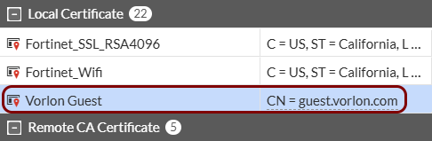
Result: Your domain or subdomain certificate will be listed in the Local Certificate section together with the domain or subdomain that it was issued for.
-
In the left-hand side menu, click on the option to open the list of certificates.
-
Configure authentication settings:
-
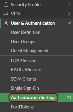
In the left-hand side menu, click on the option to open the Authentication Settings pane.
-
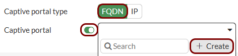
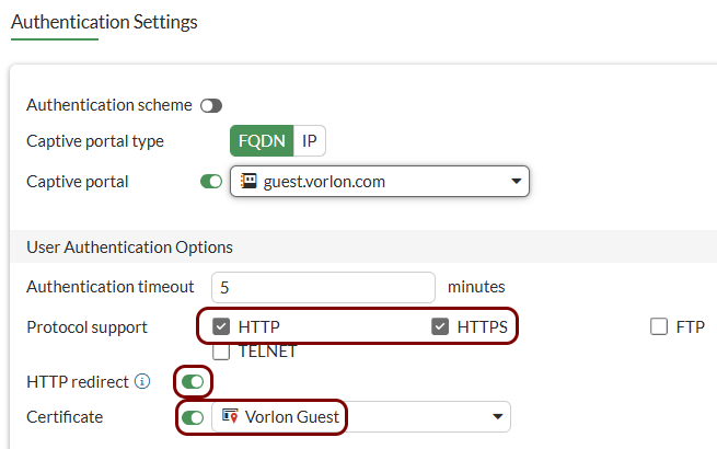
In the Authentication Settings pane, in the Captive portal type
field, select the FQDN option, activate the Captive portal
switch, and in the list, click on the Create button to create a new address
entry.
-
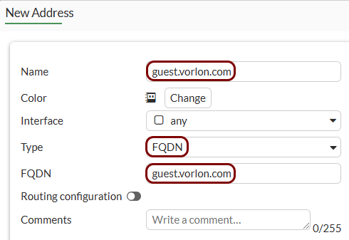
In the New Address pane, in the Name and
FQDN fields, enter the domain or subdomain name for your captive portal, and in
the Type field, select the FQDN option. Then, click on the
OK button to return to the Authentication Settings
pane.
-
In the Authentication Settings pane, activate the HTTP and
HTTPS checkboxes, activate the HTTP redirect switch,
activate the Certificate switch, and in the Certificate field,
select the TLS certificate for your domain or subdomain. Then, click on the OK button
to save your configuration.
-
In the left-hand side menu, click on the option to open the Authentication Settings pane.
Set up the local bridge mode
In this section, you will set up a Portnox captive portal in a Fortinet controller using the local bridge mode.
-
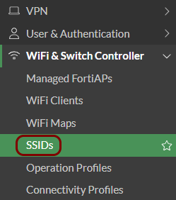
In the left-hand side menu, click on the option to open the list of SSIDs.
-
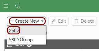
Above the SSID list, click on the Create New button,
and then select the SSID option.
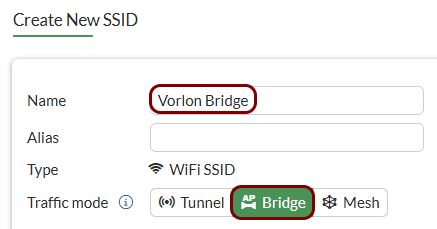
-
In the Create New SSID pane, enter the name for the configuration in the
Name field, and in the Traffic mode field, select the
Bridge option.
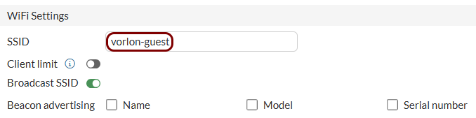
-
In the WiFi Settings section, in the
SSID field, enter the SSID.
-
In the Security Mode Settings section, in the Security mode field,
select the Open option. Then, activate the Captive Portal switch, and
in the Portal type field, select the External Authentication
option.
 Note:If the Open option is not available, go to and turn on the Wireless Open Security option.
 -
In the Authentication portal field, paste the Captive Portal URL
copied from Portnox Cloud. In the Redirect after Captive Portal field, select the
Specific URL option, and in the text field below, enter the URL that you want your users
to go to after successfully logging in to the guest network (for example, your company website).

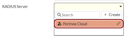
-
In the RADIUS Server list, select the RADIUS server that you created earlier.
-
Add the new guest SSID to your access point:
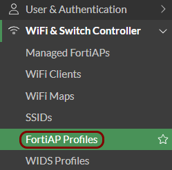
-
In the left-hand side menu, click on the option to open the list of FortiAP profiles.
-
Select the access point, and then click on the Edit button below.
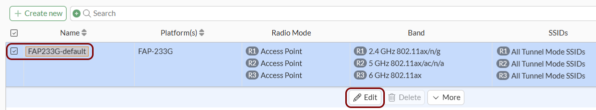
-
In the Edit FortiAP Profile pane, in the radio
section for the radio of your choice, scroll down to the SSIDs section, select the
Manual option, and select the new guest SSID.

-
In the left-hand side menu, click on the option to open the list of FortiAP profiles.
Set up the tunnel mode
In this section, you will set up a Portnox captive portal in a Fortinet controller using the tunnel mode.
-
Create the user group for guest access:
-
In the left-hand side menu, click on the option to open the list of user groups.
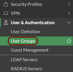
-
Above the list of user groups, click on the Create New button.
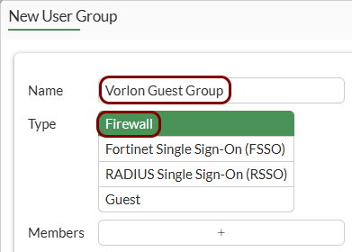
-
In the New User Group pane, in the Name field, enter a name for
this group, and in the Type field, select the Firewall
option.
-
In the Remote Groups section, click on the Add button.
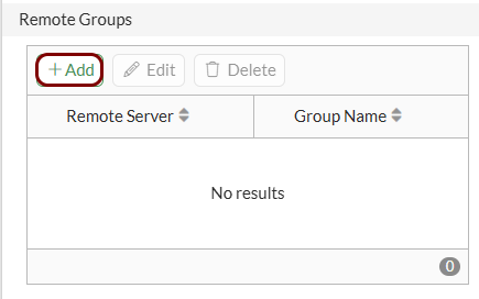
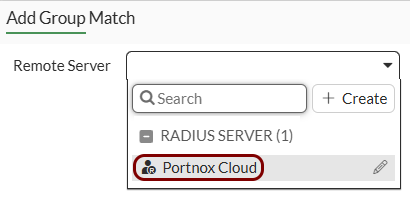
-
In the Add Group Match pane, in the Remote Server field, select
the RADIUS server that you added earlier.
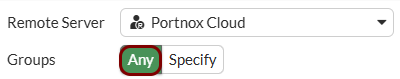
-
In the Groups field, select the Any option, and then click on
the OK button to save your configuration.
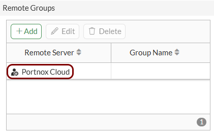
-
In the New User Group pane, confirm that the correct RADIUS server is selected in the
Remote Groups section, and then click on the OK button to
save your configuration.
-
In the left-hand side menu, click on the option to open the list of user groups.
-
Create addresses for exemptions:
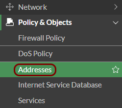
-
In the left-hand side menu, click on the option to open the list of addresses.
-
In the list of addresses, in the Address tab, click on the Create
new button.

-
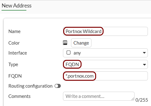
In the New Address pane, in the Name field, enter a name such
as Portnox Wildcard, in the Type field, select the
FQDN option, and in the FQDN field, enter
*.portnox.com. Then, click on the OK button to close the
New Address pane.
-
In the left-hand side menu, click on the option to open the list of addresses.
-
Create an SSID for the captive portal:
-
In the left-hand side menu, click on the option to open the list of SSIDs.
-
Above the SSID list, click on the Create New button,
and then select the SSID option.
-
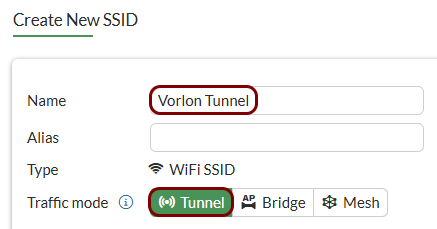
In the Create New SSID pane, enter the name for the configuration in the
Name field, and in the Traffic mode field, select the
Tunnel option.
-
In the WiFi Settings section, in the
SSID field, enter the SSID.
-
In the Security Mode Settings section, in the Security mode
field, select the Open option. Then, activate the Captive
Portal switch, and in the Portal type field, select the
Authentication option.

-
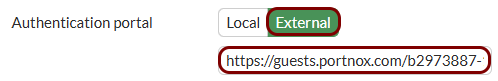
In the Authentication portal field, select the External
option, and in the text field below, paste the Captive Portal URL copied from Portnox
Cloud.
-
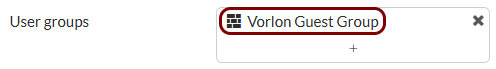
In the User groups field, click on the +
button and select the user group that you created earlier.
-
In the Exempt destinations/services field, click on the + button and select the following:
Note:If you used different names when adding addresses, use these names instead.
Tab Name Address Portnox Wildcard Address Portnox Walled Garden 1 Address Portnox Walled Garden 2 Address Portnox Guest Portal Service DNS Service DHCP 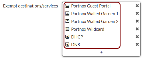
-
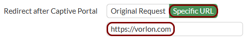
In the Redirect after Captive Portal field, select the Specific
URL option, and in the text field below, enter the URL that you want your users to go to
after successfully logging in to the guest network (for example, your company website).
-
In the left-hand side menu, click on the option to open the list of SSIDs.
-
Create security policy rules:
-
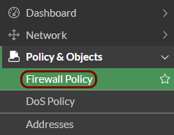
In the left-hand side menu, click on the option to open the list of firewall policy rules.
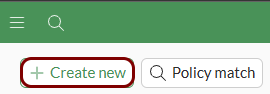
-
Above the rule list, click on the Create new button.
-
Create a rule to allow DNS traffic:
Name DNS Action ACCEPT Incoming interface your SSID Outgoing interface select the one relevant to your network configuration Source your SSID address Destination all (or specify DNS server addresses) Service DNS 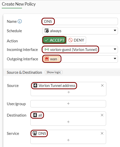
-
Create a rule to allow HTTP and HTTPS traffic:
Name Web Action ACCEPT Incoming interface your SSID Outgoing interface select the one relevant to your network configuration Source your SSID address Destination all Service HTTP, HTTPS 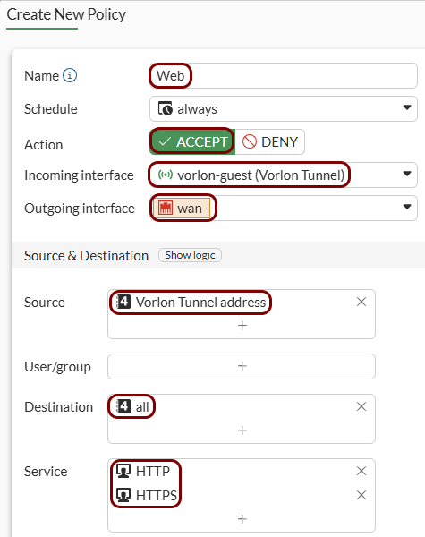
- Optional:
Create a rule to deny traffic to private networks:
Note:This rule is necessary only if the implicit rule is not set to deny all traffic.
Name Deny-Private Action DENY Incoming interface your SSID Outgoing interface select the one relevant to your network configuration Source your SSID address Destination Create new subnet addresses: 10.0.0.8/8, 172.16.0.0/12, and 192.168.0.0/16 Service ALL 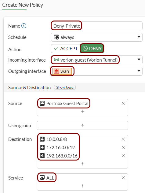
-
In the left-hand side menu, click on the option to open the list of firewall policy rules.
-
Add the new guest SSID to your access point:
-
In the left-hand side menu, click on the option to open the list of FortiAP profiles.
-
Select the access point, and then click on the Edit button below.
-
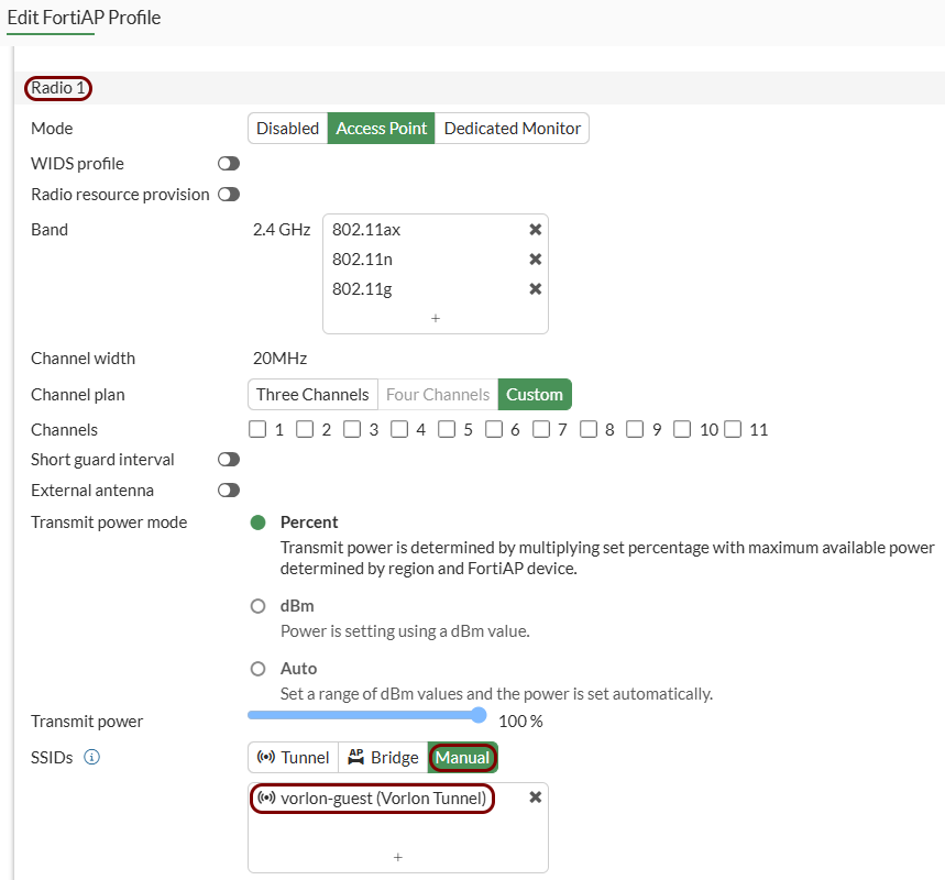
In the Edit FortiAP Profile pane, in the radio
section for the radio of your choice, scroll down to the SSIDs section, select the
Manual option, and select the new guest SSID.
-
In the left-hand side menu, click on the option to open the list of FortiAP profiles.