
Wi-Fi employee access – Cisco Wireless Controller
In this topic, you will learn how to configure a Cisco Wireless Controller to work together with Portnox™ Cloud and 802.1X RADIUS authentication for Wi-Fi connections.
Cisco Virtual Wireless Controller
This section contains an example configuration for the Cisco Virtual Wireless Controller.
-
In the top menu of the Cisco Wireless Controller web interface, click on the SECURITY
option

-
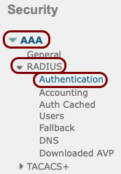
In the left-hand side menu, select the options.
-
In the RADIUS Authentication Servers pane, click on the New... button
in the top-right corner.

-
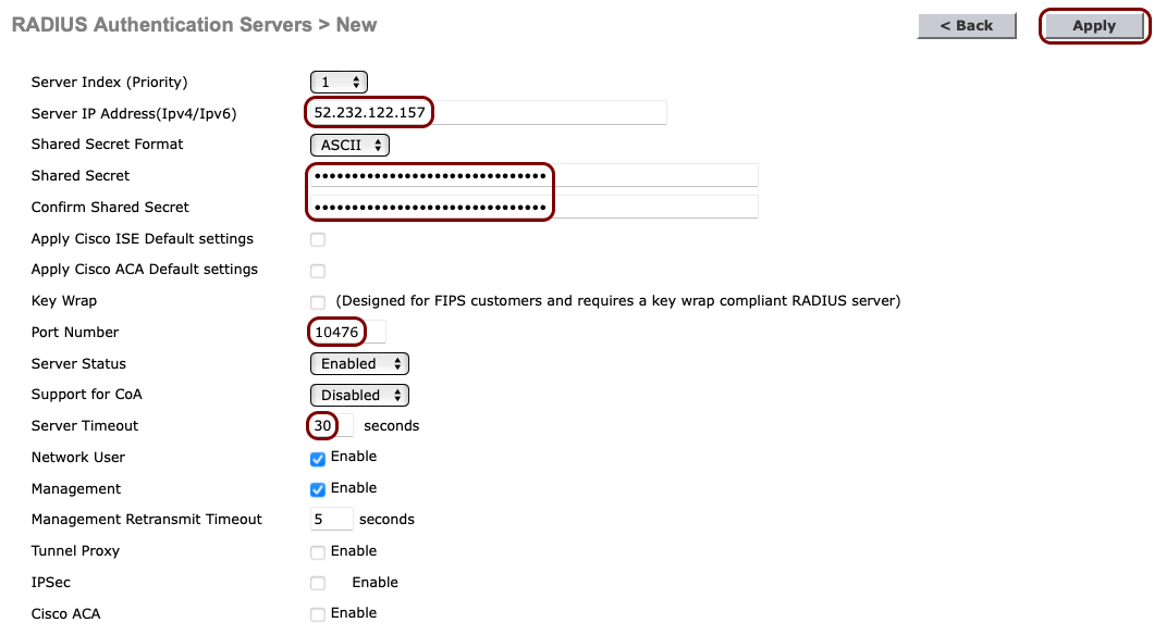
In the RADIUS Authentication Servers > New pane, enter the details of the Portnox Cloud RADIUS server that you created earlier: the Server IP
Address, the authentication Port Number, and the Shared
Secret. Set the timeout to 30 seconds. Then, click on the Apply button in the
top-right corner.
Note:The Support for CoA switch should be set to Enable if you want to use the CoA feature and/or the IPSK feature of Portnox Cloud.
-
If you use two Cloud RADIUS servers in both regions, repeat the above steps for the second RADIUS server.
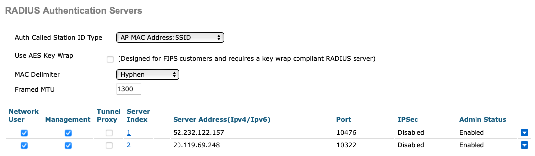
The above screenshot shows an example configuration for two Cloud RADIUS region authentication servers. Adjust the IP addresses and port numbers to your tenant configuration.
-
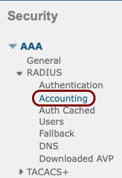
In the left-hand side menu select menu option.
-
In the RADIUS Accounting Servers pane, click on the New... button in
the top-right corner.

-
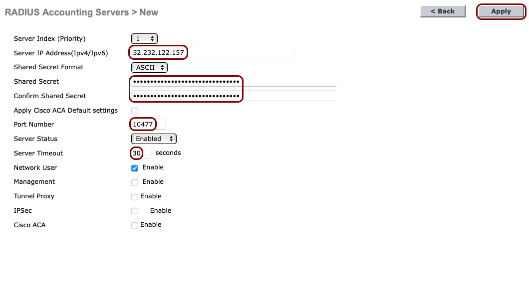
In the RADIUS Accounting Servers > New pane, enter the details of the Portnox Cloud RADIUS server that you created earlier: the Server IP
Address, the accounting Port Number, and the Shared
Secret. Set the timeout to 30 seconds. Then, click on the Apply button in the
top-right corner.
-
If you use two Cloud RADIUS servers in both regions, repeat the above steps for the second RADIUS server.
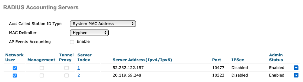
The above screenshot shows an example configuration for two Cloud RADIUS region accounting servers. Adjust the IP addresses and port numbers to your tenant configuration.
-
In the top menu of the Cisco Wireless Controller web interface, click on the WLANs
option

-
In the WLANs pane, select the Create New option from the drop-down
menu, and then click on the Go button.
 Note:Instead of creating a new WLAN, you can edit an existing WLAN by clicking on the number in the WLAN ID column.
-
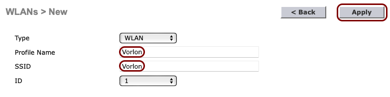
In the WLANs > New pane, enter the Profile Name and the
SSID for the secure SSID that you want to create, and then click on the
Apply button in the top-right corner.
-
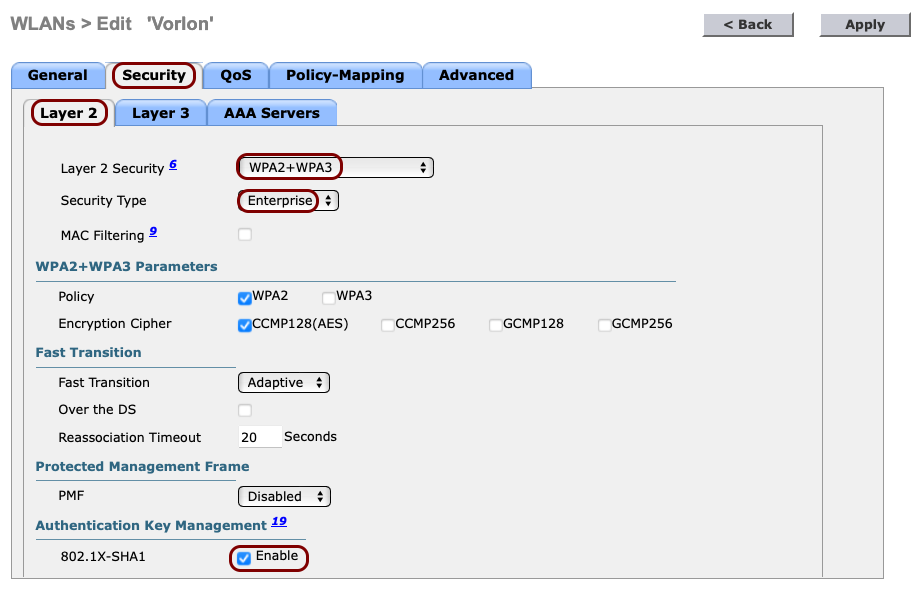
In the WLANs > Edit pane, click on the Security tab and select the
following options in the Layer 2 tab that is opened by default:
-
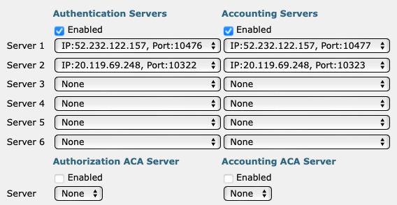
Click on the AAA Servers tab and in the Authentication Servers and
Accounting Servers columns, select the relevant servers that you defined earlier. Then,
click on the Apply button in the top-right corner.
 Important:If you want to use the IPSK feature of Portnox Cloud, additionally, activate the RADIUS Server Overwrite Interface checkbox.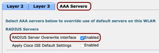
The following screenshot shows an example configuration for two Cloud RADIUS servers. Adjust the IP addresses and port numbers to your tenant configuration.
Result: Your Wi-Fi devices can now access the protected Wi-Fi network, using the Portnox Cloud RADIUS servers for authentication.
Cisco 9800
This section contains example configurations for the Cisco Catalyst 9800 Wireless Controllers and Portnox Cloud RADIUS servers, covering 802.1X, MAC Authentication Bypass (MAB), Identity Pre-Shared Key (IPSK), and RadSec.
Create an 802.1X configuration
In this section, you will create an 802.1X configuration on the Cisco Catalyst 9800, for devices such as laptops and phones that support 802.1X authentication.
-
Add the RADIUS server(s):
-
In the left-hand side menu, select the following option: .
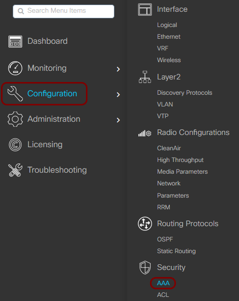
-
In the right-hand side pane, in the Servers / Groups tab, in the
RADIUS vertical tab, click on the + Add
button.

-
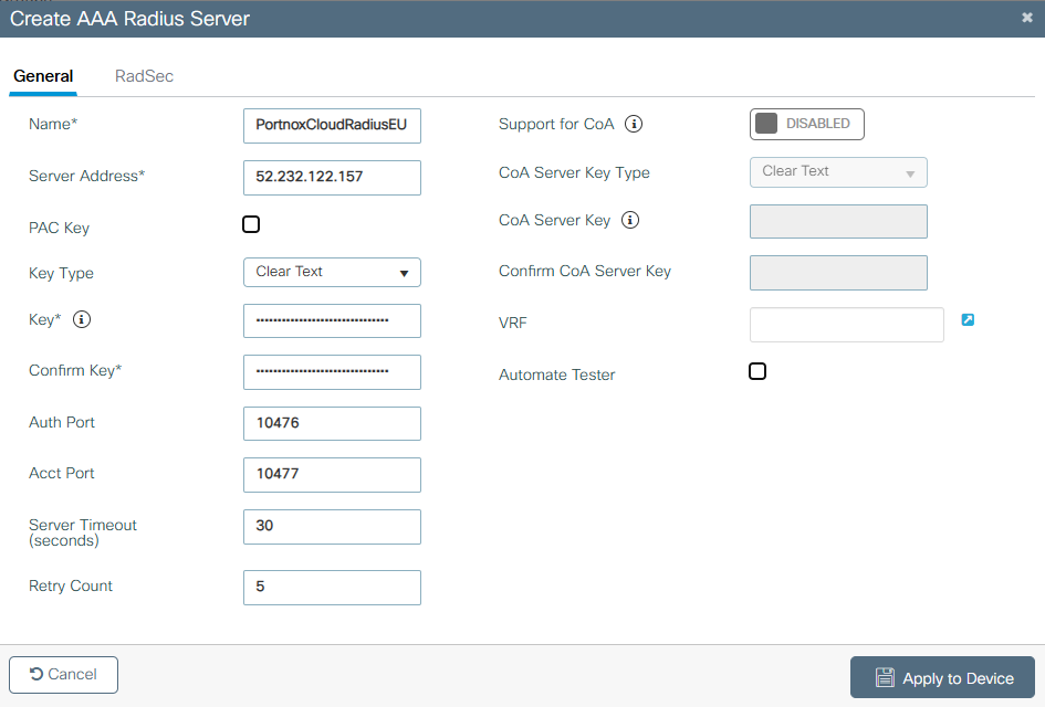
In the Create AAA Radius Server window, enter the details of the Portnox Cloud RADIUS server that you created earlier:
-
In the Name field, enter a display name for this server.
-
In the Server Address field, paste the Cloud RADIUS IP value from Portnox Cloud.
-
In the Key Type field, select the Clear Text option.
-
In the Key and Confirm Key fields, paste the Shared Secret value from Portnox Cloud.
-
In the Auth Port and Acct Port fields, paste the Authentication Port and Accounting Port values from Portnox Cloud.
-
In the Server Timeout and Retry Count fields, we recommend that you use the values 30 and 5 but you may need to adjust those values to match your ISP latency and load.
-
In the Support for CoA field, set the switch to DISABLED if using Cloud RADIUS servers. To learn more about using CoA with Local RADIUS, see the following topic: Enable the RADIUS Change of Authorization feature.
-
Then, click on the Apply to Device button to add the server.
Note:You can also do the above steps for the local RADIUS server if you prefer to use those, not Cloud RADIUS. -
-
In the left-hand side menu, select the following option: .
-
Create the RADIUS server group:
Note:You need to create a server group even if you added only one RADIUS server.
-
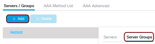
Click on the Server Groups tab on the right-hand side, and in the
RADIUS vertical tab, click on the + Add button to
create a server group.
-
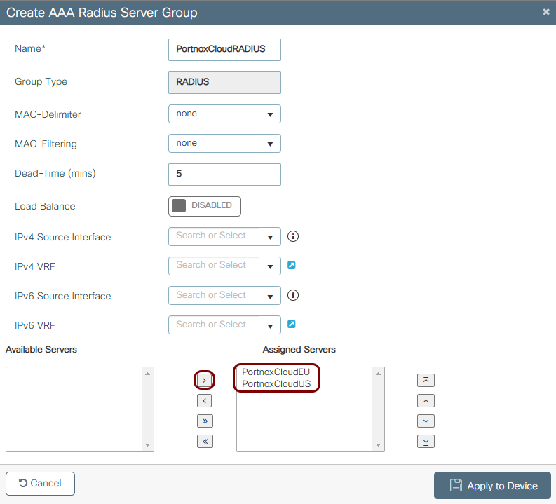
In the Create AAA Radius Server Group window, enter the display
Name for the group and using the >
button, move the names of the RADIUS servers that you created to the Assigned
Servers area, then click on the Apply to Device button.
 Note:You can use the default values for other fields or adjust them to your environment as needed.
-
Click on the Server Groups tab on the right-hand side, and in the
RADIUS vertical tab, click on the + Add button to
create a server group.
-
Create the AAA method lists:
-
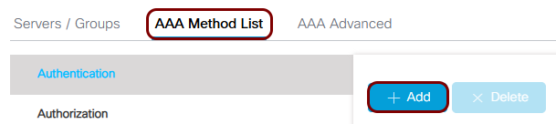
Click on the AAA Method List tab, and in the
Authentication vertical tab, click on the + Add
button.
-
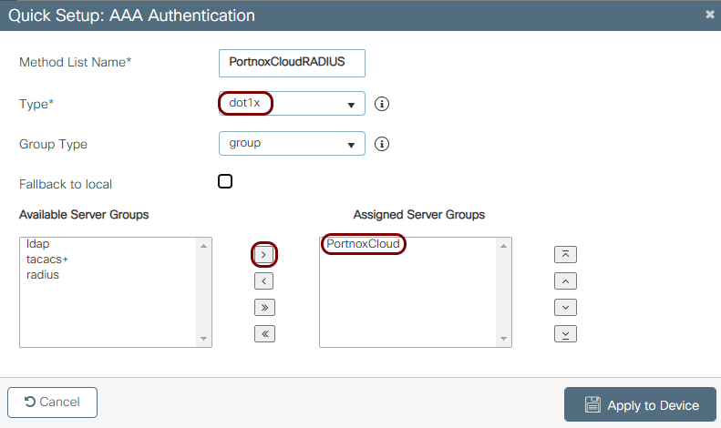
In the Quick Setup: AAA Authentication window, enter the display Method
List Name, in the Type field, select the
dot1x option, and move the server group you just created to the
Assigned Server Groups area. Then, click on the Apply to
Device button.
-
Click on the AAA Method List tab, and in the
Authentication vertical tab, click on the + Add
button.
-
Create the WLAN:
-
In the left-hand side menu, select the following option: .
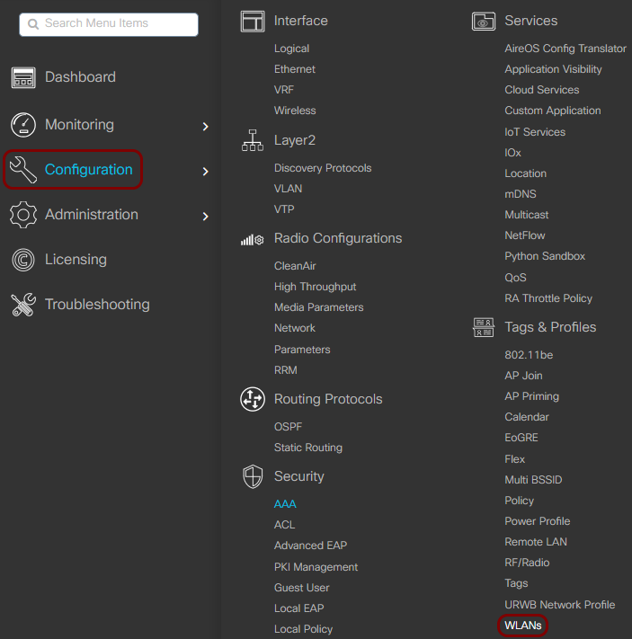
-
In the right-hand side pane, click on the + Add button.

-
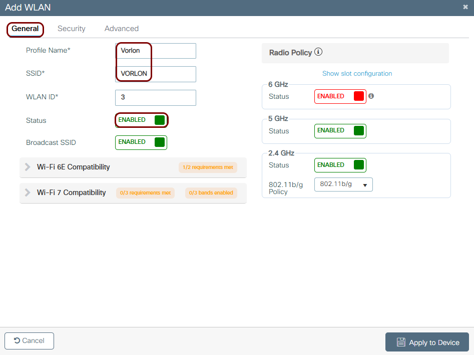
In the Add WLAN window, in the
General tab, enter the display Profile Name, the
SSID, and set the Status switch to
Enabled.
-
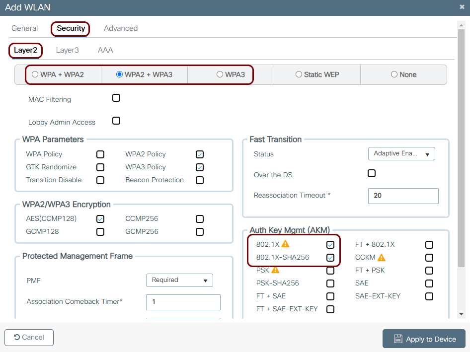
In the tab, select the WPA types that you want to support for this WLAN.
You can support WPA + WPA2, WPA2 + WPA3 or just WPA3 depending on your requirements and environment.
Whichever option you select, make sure to select 802.1X methods in the Auth Key Mgmt (AKM) area.
-
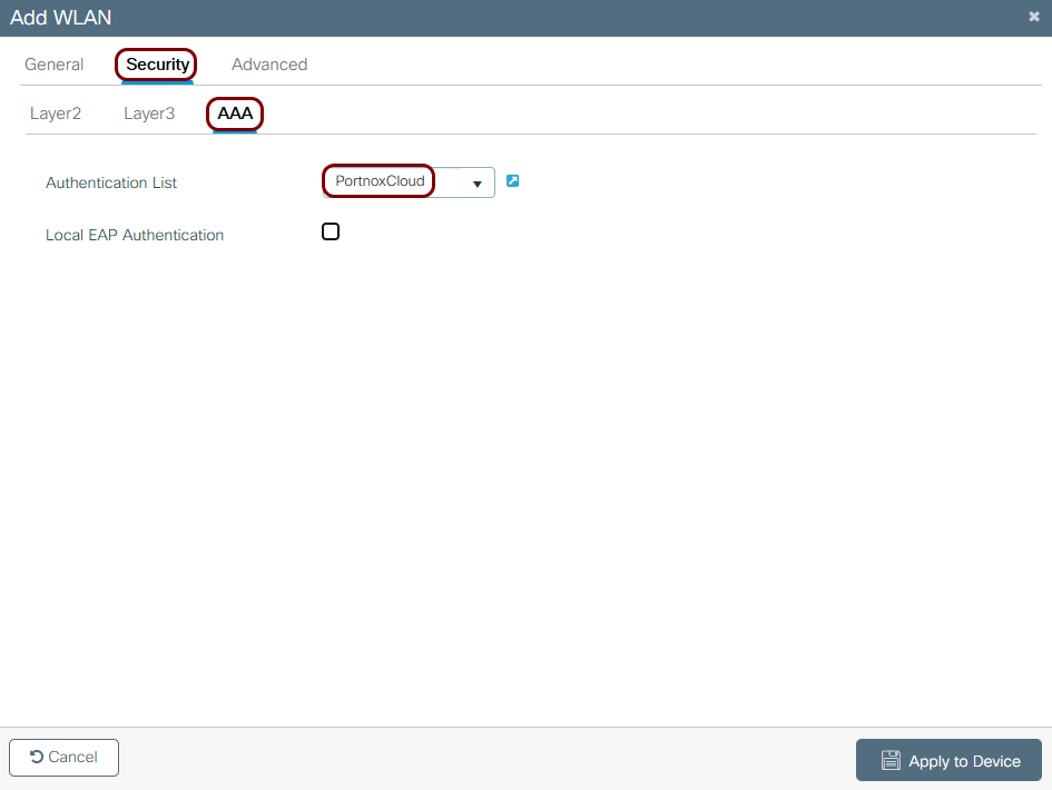
In the tab, in the Authentication List field, select the authentication
method list that you created earlier. Then, click on the Apply to Device
button.
-
In the left-hand side menu, select the following option: .
-
Create a policy profile:
-
In the left-hand side menu, select the following option: .
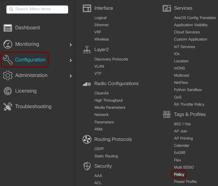
-
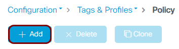
In the right-hand side pane, click on the + Add button.
-
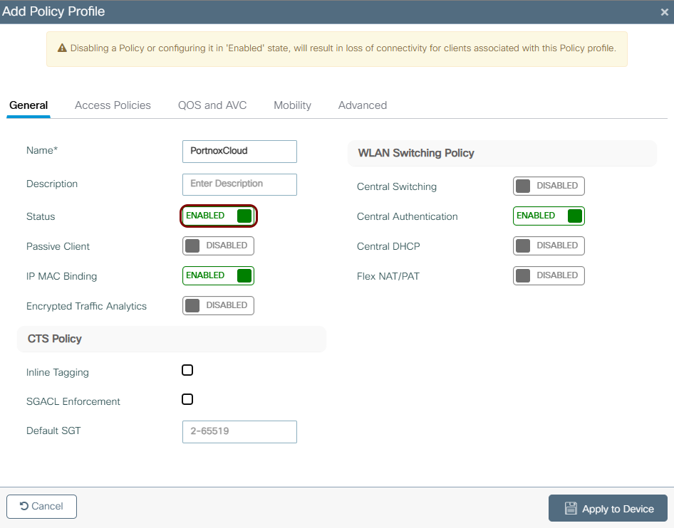
In the Add Policy Profile window, in the General tab, enter
the display Name and set the Status switch to
Enabled.
-
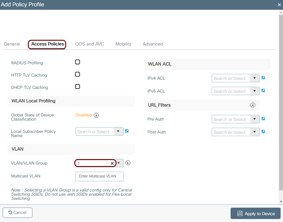
In the Access Policies tab, in the VLAN field, enter or
select the VLAN that you want clients on this WLAN to be assigned to.
- Optional:
In the Advanced tab, set the Allow AAA Override switch to
Enabled, and in the Accounting List field, select the
accounting method list that you created earlier.
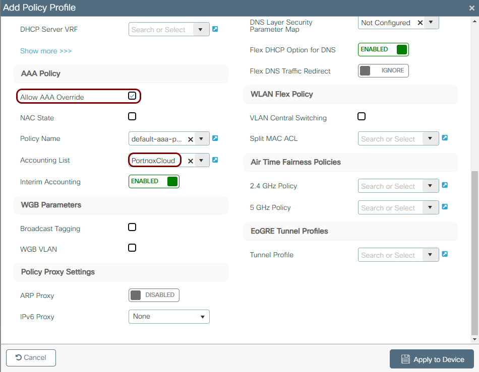 Note:Enabling Allow AAA Override is required if you want RADIUS-assigned attributes, such as a dynamic VLAN, to take effect for individual users. If you skipped creating the Authorization method list in an earlier step, this setting has no effect, and all clients will use the static VLAN configured above. Enabling this setting now also saves a step if you later want to create an IPSK configuration, which requires it.
-
In the left-hand side menu, select the following option: .
-
Create a policy tag and map the WLAN to the policy profile:
-
In the left-hand side menu, select the following option: .
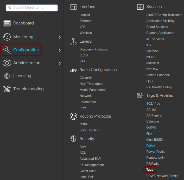
-
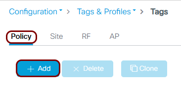
In the right-hand side pane, in the Policy tab, click on the
+ Add button.
-
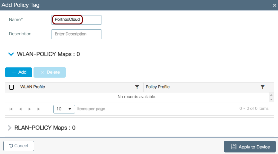
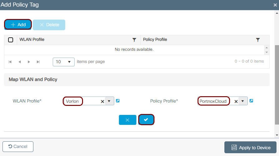
In the Add Policy Tag window, enter the display Name for
the tag.
-
In the WLAN-POLICY Maps area,
click on the + Add button, then in the WLAN Profile
field, select the WLAN that you created earlier, and in the Policy Profile field,
select the policy profile that you created earlier. Click on the ✓ button to add the mapping, then click on the Apply
to Device button to save the policy tag.
-
In the left-hand side menu, select the following option: .
-
Assign the policy tag to the AP:
-
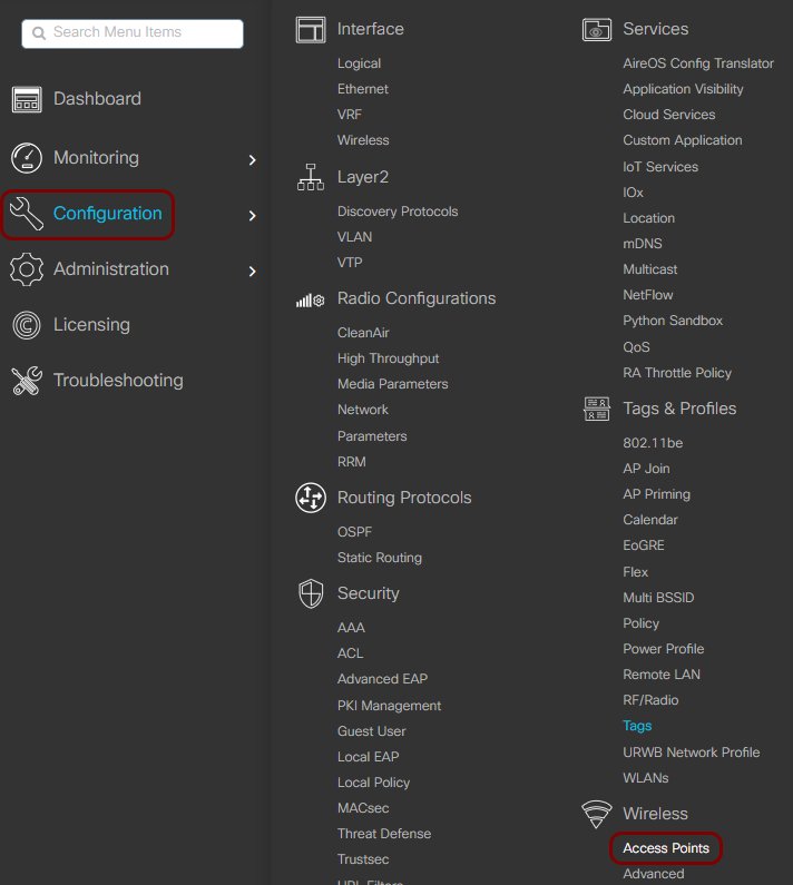
In the left-hand side menu, select the following option: .
-
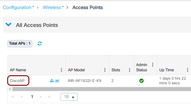
In the right-hand side pane, click on the joined access point that you want to assign the policy tag
to.
-
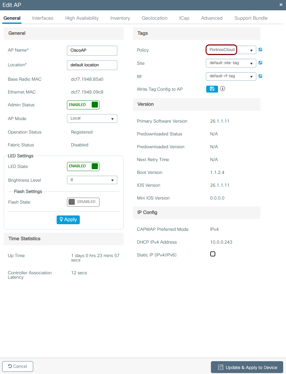
In the Edit AP window, in the General tab, in the
Tags area, in the Policy field, select the policy tag
that you created earlier.
-
In the left-hand side menu, select the following option: .
Create a MAB configuration
In this section, you will create a MAC Authentication Bypass (MAB) configuration on the Cisco Catalyst 9800, for devices such as IoT devices that do not support 802.1X.
This section reuses the RADIUS server, server group, and AAA method lists that you created for the 802.1X configuration. It also reuses the same policy profile and policy tag, adding a new WLAN-Policy map entry to the existing tag rather than creating a new one.
-
Create the WLAN:
-
In the left-hand side menu, select the following option: .
-
In the right-hand side pane, click on the + Add button.
-
In the Add WLAN window, in the
General tab, enter the display Profile Name, the
SSID, and set the Status switch to
Enabled.
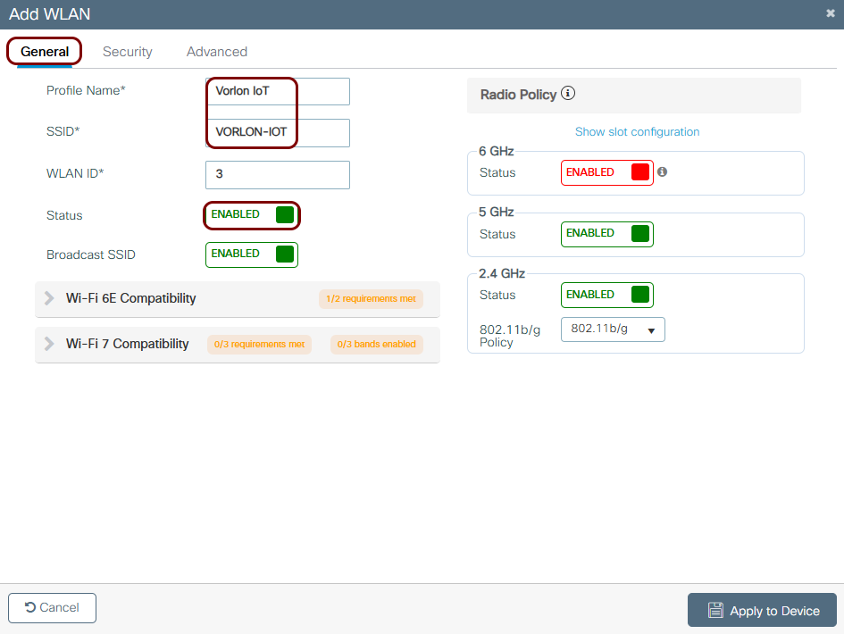 Note:Use a different Profile Name and SSID than the ones you used for the 802.1X configuration. A Cisco 9800 WLAN can use only one authentication method, so 802.1X and MAB always need separate WLANs.
 -
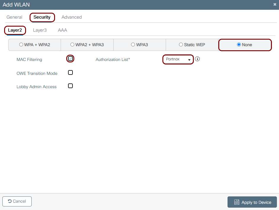
In the tab, select the None option, deactivate the OWE
Transition Mode checkbox, activate the MAC Filtering checkbox,
and in the Authorization List field, select the authorization method list that
you created earlier.
-
In the left-hand side menu, select the following option: .
-
Add the WLAN to the existing policy tag:
-
In the left-hand side menu, select the following option: .
-
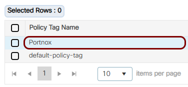
In the right-hand side pane, in the
Policy tab, click on the row of the policy tag that you created for the
802.1X configuration.
-
In the WLAN-POLICY Maps area,
click on the + Add button, then in the WLAN Profile
field, select the WLAN that you created earlier, and in the Policy Profile field,
select the policy profile that you created earlier. Click on the ✓ button to add the mapping, then click on the Apply
to Device button to save the policy tag.
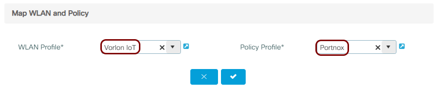 Note:In the Policy Profile field, select the same policy profile that you used for the 802.1X WLAN, unless you want MAB devices to land on a different VLAN.
-
In the left-hand side menu, select the following option: .
Result: You created a separate SSID that authenticates devices by their MAC address using the Portnox Cloud RADIUS servers on the basis of MAC-based accounts. Since the access point already has the policy tag assigned, from the 802.1X configuration, no additional AP tagging step is needed.
Create an IPSK configuration
In this section, you will create an Identity Pre-Shared Key (IPSK) configuration on the Cisco Catalyst 9800, for devices that need a pre-shared key tied to their identity, rather than a single shared network-wide password.
This section reuses the RADIUS server, server group, and AAA method lists that you created for the 802.1X configuration. It also reuses the same policy tag, adding a new WLAN-Policy map entry rather than creating a new one.
-
Create the WLAN:
-
In the left-hand side menu, select the following option: .
-
In the right-hand side pane, click on the + Add button.
-
In the Add WLAN window, in the
General tab, enter the display Profile Name, the
SSID, and set the Status switch to
Enabled.
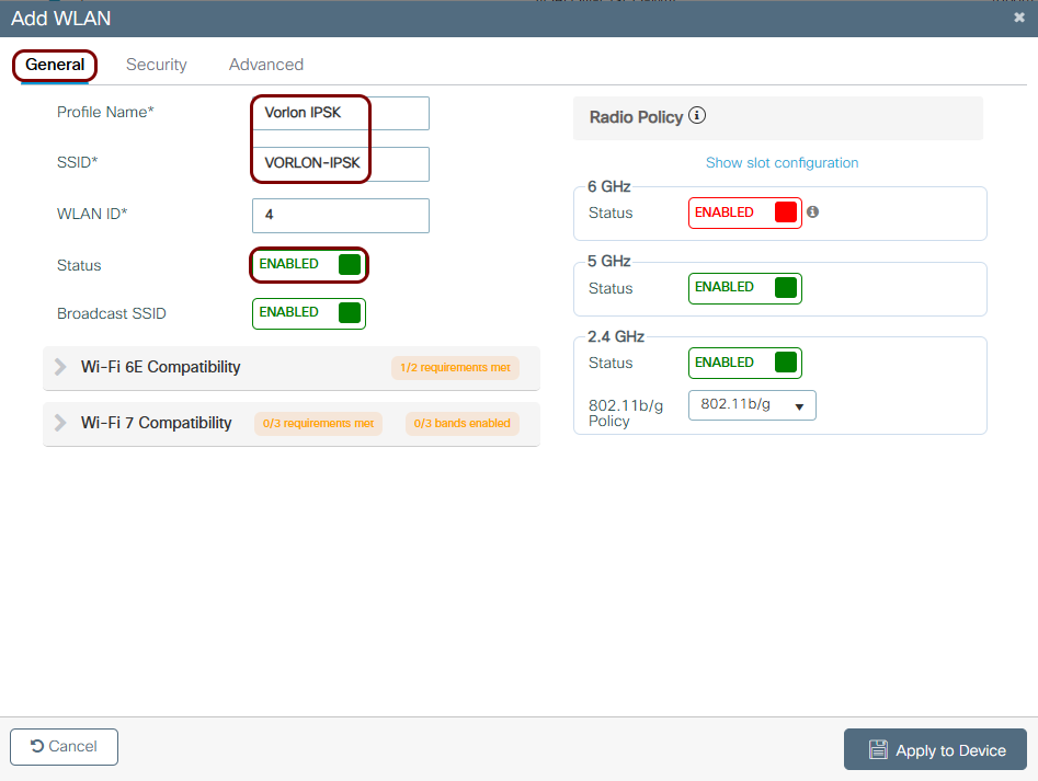 Note:Use a different Profile Name and SSID than the ones you used for the 802.1X and MAB configurations. A Cisco 9800 WLAN can use only one authentication method, so IPSK always needs its own WLAN.
 -
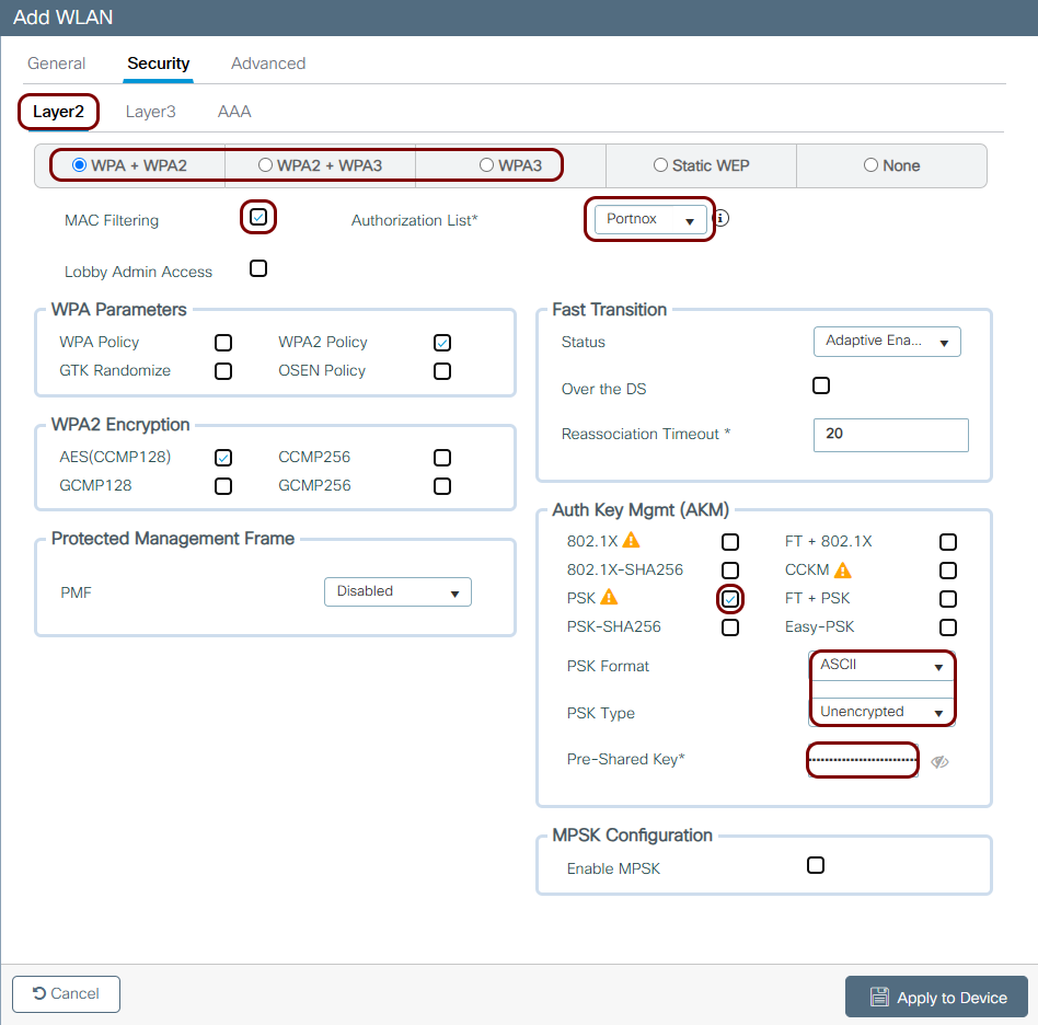
In the tab, select the WPA + WPA2 or WPA2 + WPA3
option. Activate the MAC Filtering checkbox, and in the Authorization
List field, select the authorization method list that you created earlier. In the
Auth Key Mgmt (AKM) area, deactivate the 802.1x
checkbox and activate the PSK checkbox (or SAE if you
selected WPA3). In the Pre-Shared Key field, enter any placeholder value: the WLC
never actually uses it, since Portnox Cloud supplies the real key for each device over RADIUS. Then,
click on the Apply to Device button.
-
In the left-hand side menu, select the following option: .
-
Enable AAA override on the policy profile:
Warning:Without this setting, the WLC ignores the pre-shared key that Portnox Cloud returns over RADIUS, and falls back to the placeholder key you entered on the WLAN. The client device then fails the 4-way handshake and disconnects immediately, even though RADIUS authorization succeeded.
-
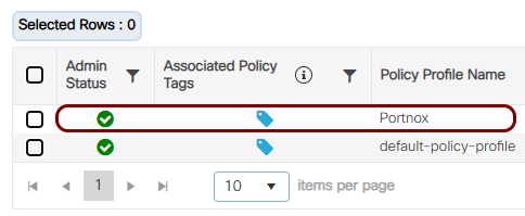
In the left-hand side menu, select the following option: .
-
In the right-hand side pane, click on the row of the policy profile that you created for the 802.1X
configuration.
-
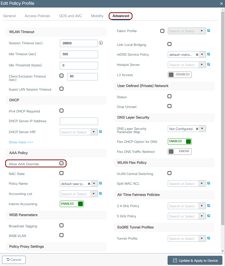
In the Advanced tab, set the Allow AAA Override switch to
Enabled if it is not already, then click on the Update & Apply
to Device button.
-
In the left-hand side menu, select the following option: .
-
Add the WLAN to the existing policy tag:
-
In the left-hand side menu, select the following option: .
-
In the right-hand side pane, in the
Policy tab, click on the row of the policy tag that you created for the
802.1X configuration.
-
In the WLAN-POLICY Maps area,
click on the + Add button, then in the WLAN Profile
field, select the WLAN that you created earlier, and in the Policy Profile field,
select the policy profile that you created earlier. Click on the ✓ button to add the mapping, then click on the Apply
to Device button to save the policy tag.
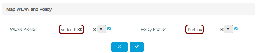 Note:In the Policy Profile field, select the same policy profile that you enabled AAA override on in the previous step.
-
In the left-hand side menu, select the following option: .
Result: You created a separate SSID that assigns a unique pre-shared key to each device, based on Portnox Cloud MAC-based accounts. Since the access point already has the policy tag assigned, from the 802.1X configuration, no additional AP tagging step is needed.
Create a RadSec configuration
This is an optional task. Follow this task only if you want to connect to Portnox Cloud RADIUS servers using RadSec instead of, or in addition to, a standard RADIUS connection.
-
Turn on RadSec connections for your Cloud RADIUS server(s).
-
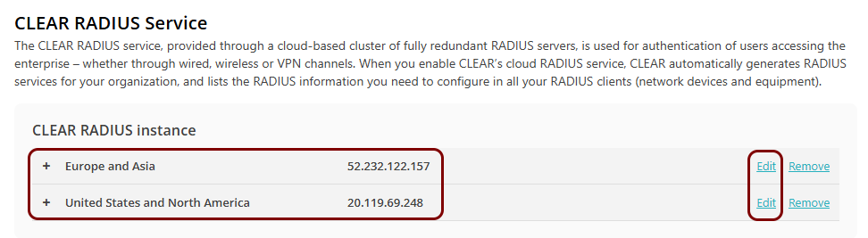
Go to and select the Cloud RADIUS server that you want to connect to using RadSec. Then, click on
the link.
-
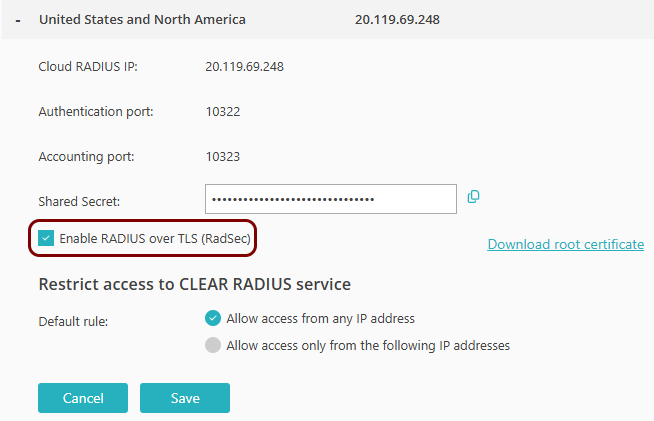
Activate the Enable RADIUS over TLS (RadSec) checkbox.
-
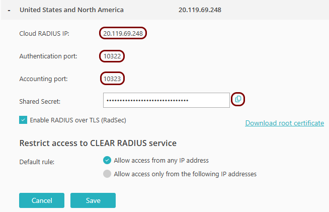
Copy the following information and store it, for example, in a text file. You will need this information
later on in the configuration process:
- Cloud RADIUS IP
- Authentication port
- Accounting port
-
Go to and select the Cloud RADIUS server that you want to connect to using RadSec. Then, click on
the link.